Contents
- Overall picture
- Core allocation and the M33
- Sample rates and signal path
- Inter-core communication (shared ring · RPMsg)
- Latency budget
- Holter storage · trends
- Alarm engine
- State machine
- Power-on self-test
- Cloud · security · updates
- Software safety-class separation · modules
- Development order · measurement list
- Test-bench firmware (ESP32-S3 + ADS1293)
- Test-bench verification results
1. Overall picture
The processor is the NXP i.MX 95. The measurement section that touches the patient (patient island) is isolated and connects to the processor through digital isolators (ISO7762). The processor chip set (i.MX 95 · AFE159RP8 · AFE4490 · stage-2 RM44L920) is Confirmed specification; the core allocation below is a Default.
 Patient island (isolated, CF)         │ Non-patient side (i.MX 95 SoM)
 ──────────────────────────────────────┼───────────────────────────────────────
 AFE159RP8 (ECG 8ch, 10 electrodes, pace on-chip) ─ISO7762#1─ LPSPI-A ┐
 AFE4490   (SpO2, PRF 500 Hz)            ─ISO7762#2─ LPSPI-B ├─► Cortex-M7 800 MHz (FreeRTOS)
 V1/V5 switch · sim/signal switch state  ─(isolated GPIO)────┘   acquisition·filters·QRS·pace·SpO2
 (+option) NIBP module UART · Resp (AFE built-in)                   ·alarm decision·alarm tone
                                                    │ shared DDR ring (waveforms) + RPMsg (commands·events)
                                                    ▼
                         Cortex-A55 ×6 (Linux, Yocto)  display (Qt)·Holter·trends·cloud·OTA·logs·permissions
                         Cortex-M33 (NXP SM)           power·clocks·reset·PMIC·fault reaction (per-LM reset)
 External: TPS3430 window watchdog (kicked by M7) → WDO → backup buzzer + A55 GPIO   [stage 2] RM44L920 safety MCU (SPI)
 LTC1760 + smart packs A/B (SMBus, owned by M7) · VSYS undervoltage comparator → M7 IRQ
Three core-allocation principles Default
- The patient-safety path (acquisition → decision → alarm tone) is closed within the M7 alone. Even if Linux dies, the sound still plays.
- Linux only does "display, store, send." If Linux stalls, the M7 notices and sounds a high-priority "display failure."
- If the M7 stalls, the System Manager (SM) resets only the M7; meanwhile the TPS3430 sounds the backup buzzer and the A55 turns the waveforms gray.
2. Core allocation and the M33
Changed in design review — monitoring and alarm backup cannot be placed on the M33. On the i.MX 95, the M33 is a core dedicated to the NXP System Manager. Original text of the NXP imx-sm documentation (sm/doc/arch.md):
- "SM owns the M33 core and does not support customers adding workloads to this core."
- "the Cortex-M33 is not available to run customer applications. … additional customer functionality may interfere with the real-time response of the SM."
So the Default was set as follows. The M33 is left running NXP SM as-is (no code changes, configuration files only), and the SM's fault reactions (FCCU · watchdog → reset only the affected LM) are used as "primary hardware supervision." The SM configuration already contains the reactions M7_LOCKUP → M7(LM1) reset and WDOG3/WDOG4 → AP(LM2) reset. Monitoring and alarm backup: stage 1: M7 ↔ A55 mutual supervision + external window watchdog TPS3430 + backup buzzer; stage 2: handed over to the RM44L920.
Responsibilities by core Default
| Core | OS | Responsibilities |
|---|---|---|
| M7 (800 MHz, per SoM vendor) | FreeRTOS + MCUXpresso SDK + RPMsg-Lite (alternative: Zephyr) | AFE159RP8 · AFE4490 acquisition, common time base, pace detection, decimation, dual adaptive notch, HPF/LPF, QRS · HR, SpO2 · PR · PI, (option) respiration · NIBP, alarm condition decision · prioritization · alarm tone synthesis, lead-off · sensor-off, power monitoring (LTC1760 · packs · VSYS), kicking the external watchdog, A55 supervision |
| M33 | NXP SM (bare metal, no in-house code) | Power · clocks · reset · PMIC, TRDC resource isolation, FCCU fault reaction, reset-reason logging |
| A55 ×6 | Linux (NXP vendor kernel) | Qt 6 display, Holter recording, trend DB, alarm display · operation · logging, settings · permissions, cloud sync, OTA · USB updates, service mode, security |
| RM44L920 (stage 2) | TI HALCoGen + in-house (TBD) | Dual cross-check of alarm decisions, backup alarm tone, external watchdog management, fail-safe decisions |
Resource ownership (fixed by SM configuration)
| Resource | Owner | Notes |
|---|---|---|
| LPSPI ×2 (dedicated ECG · PPG buses) | M7 | AFE4490 cannot tri-state when not selected, so bus sharing is prohibited |
| DRDY · ADC_RDY interrupt GPIOs, switch-state GPIOs | M7 | |
| One general-purpose timestamp timer | M7 | Common ECG · PPG time base |
| SAI or PWM + alarm-tone amplifier | M7 | Sound must play independently of Linux |
| I²C (SMBus) → LTC1760 · packs A/B | M7 | Because power alarms are decided by the M7 |
| (option) NIBP UART | M7 | The M7 must know to flag ECG noise while the pump is running |
| WDOG5 | M7 (SM fault reaction) | WDOG5 → LM_RESET lm 1 |
| PMIC I²C, clocks, reset | SM | |
| Display (LVDS) · GPU · eMMC · USB · Wi-Fi/BT · GbE ×2 · backup buzzer GPIO | A55 | |
| ELE (EdgeLock Secure Enclave) | Boot chain · A55 |
Resource budget (calculated · default)
| Item | Value | Notes |
|---|---|---|
| M7 ITCM / DTCM | 256 KB / 256 KB | Per Zephyr dts. NXP reference manual original Unverified |
| M7 code placement | ITCM (DSP · ISR), large tables in DDR | Default |
| M7 load estimate | 8 kHz interrupt (≤ 5 µs each → 4 %) + decimation FIR about 0.75 M MAC/s + notch · QRS (500 SPS) → under 10 % | Calculated. To be measured with the DWT cycle counter |
| Shared DDR reserved region | 32 MiB (rings about 23.2 MiB + margin) | Calculated |
3. Sample rates and signal path
Why 8 kSPS
- IEC 60601-2-27 requires pace pulses to be excluded from HR calculation. Range ±2 to ±700 mV, 0.1 to 2 ms (the lower width limit is taken at the wider-coverage 0.1 ms)
- TI ADS1298 datasheet: software detection needs "8 kSPS or more." Published figures: 8 kHz Se 95.5 % · 16 kHz 97.1 % · 32 kHz 99.3 % (CinC 2018)
- The AFE159RP8 has an on-chip 4-lead pace algorithm + 128 kSPS pace output. However, the public version is a summary, so the detection output format, width and amplitude range are Unverified
Default All ECG channels are acquired at 8 kSPS 24-bit. Pace uses on-chip detection (primary) + M7 software detection (secondary confirmation). If the detailed datasheet confirms that on-chip detection fully meets the requirements, lowering to 2 kSPS will be considered; until then, fixed at 8 kSPS.
Path inside the M7
AFE159RP8 8 kSPS × 8ch × 24bit ── DRDY ISR → LPSPI DMA ─┐
                                                         ├─ ① timestamping (general timer 32bit, sample number u64)
AFE4490 500 SPS × 6 streams ── ADC_RDY ISR → LPSPI ──────┘
   ├─ ② pace: chip flag + 8 kSPS slope · width check → event {sample number, lead, width}
   ├─ ③ pace blanking: fill the pulse interval by linear interpolation at 8 kSPS
   ├─ ④ decimation 8000 → 2000 → 500 SPS (2-stage linear-phase FIR, ÷4·÷4)
   │      group delay estimate: 31 taps (8k) 1.9 ms + 63 taps (2k) 15.5 ms ≈ 17.4 ms (calculated)
   ├─ ⑤ "raw data" branch → Holter storage (500 SPS 24bit, pre-notch · pre-HPF) + calib row
   ├─ ⑥ HPF → dual adaptive notch (60·120 Hz) → LPF   (keep both pre- and post-notch — for comparison view)
   ├─ ⑦ QRS detection (separate 5–15 Hz band, independent of notch state)
   │      pace events excluded from HR · marked only when "Paced=Yes"
   └─ ⑧ PPG: 500 SPS → 5-sample average 100 SPS → band-pass filter → R · SpO2 · PR · PI. 1 s period
Reason for going down to 500 SPS: the previously designed dual-notch coefficients are based on fs = 500 Hz and can be reused as-is. Blanking length and FIR tap counts will be set by measurement in the signal-processing design.
Channel assignment Default
| AFE channel | Basic 5 electrodes | 12-lead option |
|---|---|---|
| CH1 | I (LA−RA) | I |
| CH2 | II (LL−RA) | II |
| CH3 | III (LL−LA) direct Confirmed | V1 |
| CH4 | V (V1/V5 switch) | V2 |
| CH5~8 | Self-diagnostic rotation (internal test signal → calib row, supply · temperature) | V3~V6 |
Downsampling for display
- Each column (px) is drawn as a min/max vertical line to preserve QRS peaks. Simple decimation is prohibited
- PPG 100 SPS uses linear interpolation between neighboring samples
- Screen row order is 6 rows fixed: calib · lead1 · lead2 · lead3 · SpO2 · pulse Confirmed. The screen position of the V lead (V1/V5) is TBD; it is always included in the recording
4. Inter-core communication — shared memory ring + RPMsg
| Path | What | Reason |
|---|---|---|
| Shared DDR ring (SPSC, M7 writes · A55 reads) | Waveforms (raw · processed · PPG) · beat/pace events | High volume (tens of kB per second). Zero copy. The A55 polls the write index every vsync → latency ≤ 1 frame |
| RPMsg | Commands · settings · alarm state · numerics · heartbeat | Message-based, ordering guaranteed. Linux default buffer 512 B |
RPMsg common header (24 B, little-endian) Default
| Field | Type | Description |
|---|---|---|
| magic | u16 | 0xEC61 |
| ver | u8 | Protocol version (checked in HELLO; device failure if different) |
| type | u8 | Message type |
| len | u16 | Body length (≤ 472 B = 512 − RPMsg header 16 − 24) |
| flags | u16 | bit0 response requested, bit1 retransmission |
| seq | u32 | Sender sequence number. Detects gaps · reordering |
| t_idx | u64 | Global sample number at 500 SPS (common time base) |
| crc | u32 | CRC-32C (over header + body with the crc field set to 0) |
Two endpoints: ekg-ctrl (A55 → M7 commands, M7 responses) · ekg-evt (M7 → A55 events · status).
Main messages Default
| type | Name | Direction · period | Key points |
|---|---|---|---|
| 0x01/0x02 | HELLO / HELLO_ACK | At startup | M7 firmware version · protocol version · ring layout table ↔ release number. If different, high-priority "software mismatch" |
| 0x10 | HB_M7 | M7→A55 10 Hz | Uptime, device state, ring write index, CPU load, sample loss count, notch state |
| 0x11 | HB_UI | A55→M7 10 Hz | Counter of frames actually flipped, list of alarm IDs currently shown on screen |
| 0x20~0x22 | CFG_SET / ACK / SNAPSHOT | Request · response · 1 min | Send safety settings and read back the applied value to confirm. Rejected if out of the allowed range |
| 0x30~0x32 | ALARM_STATE / CMD / CMD_ACK | Immediately on change + 1 Hz | Decisions are made by the M7. The A55 only does pause (default 2 min) · acknowledge · latch release |
| 0x40 | NUMERICS | 1 Hz | HR (source ECG/PPG/SIM), PR, SpO2 ("reference value · not calibrated" flag), PI, valid/invalid per parameter |
| 0x50~0x52 | DEVICE_STATE · POWER_STATUS · SELFTEST | On change · 1 Hz · POST | Device state, pack A/B remaining charge · temperature · SOH, self-test results |
| 0x60 | LEAD_STATUS | On change | Lead-off per electrode, V1/V5 switch position, sim/signal position, SpO2 sensor status |
| 0x70 · 0x80/0x81 | FAULT · SHUTDOWN_REQ/READY | On occurrence | Fault code · confirmation that Holter file is closed before shutdown |
| 0x90 | SERVICE_CMD | Service mode only | Rejected in measurement mode |
| 0xA0 | TIME_SYNC | 1 min | UTC ↔ t_idx mapping (for records. Alarm decisions use only t_idx) |
Shared memory rings (calculated · default)
All rings have power-of-two lengths; indices are the global sample number u64 masked. The M7 writes all the data, then a memory barrier → write-index update. CRC-32C per block (20 ms = 10 samples).
| Ring | Format | Length | Size | Use |
|---|---|---|---|---|
| R_RAW | int32 × 8ch, 500 SPS (pre-notch · pre-HPF) | 2¹⁹ = 17.5 min | 16 MiB | Holter · calib. Holds the recording while Linux restarts |
| R_PRE / R_POST | float32 × 8ch × 2 | 2¹⁶ = 131 s | 4 MiB | Display, notch comparison view, freeze |
| R_PPG | {red, ir int32, pleth float}, 100 SPS | 2¹⁷ = 21.8 min | 2.5 MiB | Rows 5 · 6, Holter |
| R_EVT | 32 B events | 2¹⁴ | 512 KiB | Heart icon sync, annotations |
| Control block | Layout table · write indices · overwrite counters | — | 4 KiB | |
| Total | about 23.2 MiB → 32 MiB reserved |
The reserved region is non-cacheable. Whether this DDR region survives intact when only the A55 is reset is Unverified — measurement item S-01.
5. Latency budget
Electrode → screen (calculated · default)
| Stage | Latency |
|---|---|
| AFE159RP8 internal digital filter | Unverified |
| 2-stage decimation FIR | ≈ 17.4 ms |
| M7 block processing (20 ms blocks) | ≤ 20 ms |
| Shared ring → A55 polling | ≤ 16.7 ms |
| Fixed display delay D (absorbs QRS detection delay, heart icon sync) | 300 ms initial value |
| Render + page flip (double buffer, 2 frames) | ≤ 33 ms |
| Total | about 390 ms + AFE latency |
Alarms Default
| Path | Budget |
|---|---|
| Heart rate high/low limits, asystole (condition delay + signal generation delay) | Total ≤ 10 s (condition decision ≤ 8 s + sound start ≤ 1 s + margin) — voluntarily adopting the IEC 60601-2-27 criterion, which does not apply to home use |
| Lead-off · saturation indication | ≤ 1 s (standard ≤ 10 s) |
| SpO2 update stalled | Low priority if > 30 s |
| Battery depletion | High priority at 20 min remaining (standard: "at least 5 min before") |
| M7 decision → A55 screen display | ≤ 50 ms |
| M7 decision → cloud · caregiver notification | Best effort (no guarantee) — not counted as part of the alarm system |
6. Holter storage · trends
Principles
- The on-device record is the master copy; the cloud holds a copy
- The stored signal is raw data before notch · HPF (500 SPS 24-bit). Filters are reapplied when viewing → can be re-analyzed
- Basic 5 electrodes, 4 channels: 518.4 MB per day; 12-lead, 8 channels: 1.04 GB per day (calculated) → eMMC pSLC 32 GB or more
1-second blocks Default
Fixed-size slots: 4 channels 8 KiB, 8 channels 16 KiB (eMMC 4 KiB aligned). Segment files of 1 hour = 3600 slots are preallocated so that file metadata does not change during writing.
| Position | Fields | Size |
|---|---|---|
| Header | magic 'EKGB', format version, session UUID, block sequence number, first sample number, UTC + monotonic time, sampling (500), channel count · map · scale, copy of filter settings, notch state, flags (SIM · lead-off · Paced · charging) | 128 B |
| ECG | 500 × N channels × 3 B (24-bit packed) | 6,000 B (4ch) / 12,000 B (8ch) |
| PPG | 100 × 2 × 3 B (red · IR) | 600 B |
| Trend | HR · PR · SpO2 · PI · (RR · NIBP) for this second + validity flags | 32 B |
| Annotation TLV | Beats (type "for reference"), pace instants (8 kSPS resolution), lead changes, V1/V5 switching, alarm start · end, patient button, time correction | Variable |
| Trailer | CRC-32C + hash chain containing the previous block's SHA-256 | 36 B |
- Pace raw waveforms are not stored at high speed; only the instants are recorded (a 128 kSPS raw waveform would be about 88 GB per day)
- Writing: one-slot
pwrite+fdatasyncevery second. The writer thread shares no locks with the render thread - File system: ext4
data=ordered+ preallocation + fdatasync per block as default, F2FS as alternative. Final choice after repeated forced power cuts followed by hash-chain checks - Data lost: only in a sudden outage where both battery packs disconnect simultaneously, ≤ 1–2 s. Zero on the normal shutdown path
- Recovery at startup: check CRC · hash chain of the last segment from the end → a broken tail is marked "not recorded" + "recording gap" annotation. The gap is not filled in
- Export: EDF+/BDF (24-bit) or WFDB-FLAC by default; ISHNE · DICOM Ambulatory (16-bit) for compatibility. Master blocks stay as they are
Trend DB Default
- The master is the 1-second trend record inside the Holter blocks. If the DB is corrupted, it is rebuilt from the blocks
- SQLite for queries (WAL, synchronous=FULL) — 1-second table + 1-min · 5-min · 1-hour aggregate tables
- Retention 1 year (5–6 parameters at 1 s, 2 B → 315–378 MB, calculated). Window 30 min to 7 days
- SpO2-derived indices are labeled "reference value · not calibrated"
7. Alarm engine (IEC 60601-1-8 priorities)
- M7
AlarmCore: condition decision, prioritization, latching, pause timer, alarm tone synthesis. If no settings have arrived, it runs with compiled-in default limits - A55
AlarmUI: visual signals (color · blinking · text), operation, alarm log, remote supplementary notification. It makes no decisions - Visual cross-check: the M7 receives the "displayed alarm ID list" in HB_UI; if an active alarm is absent from the screen for more than 2 s, "display failure" (high)
- Stage 2: the RM44L920 decides independently from the same inputs and cross-checks against the M7 result
Priorities · signals Default
| Item | High | Medium | Low |
|---|---|---|---|
| Color | #FF0000 fill | Yellow fill + black text | Cyan fill + black text |
| Blinking | Keep current 1 Hz (until the standard's original text is checked) | Same | None |
| Sound | 10-pulse burst | 3 pulses | 1–2 pulses |
- Sound frequency: main energy 500–1000 Hz, speaker + synthesized waveform (considering age-related hearing loss, a 4 kHz piezo alone is not used)
- Pause default 2 min, automatically restored at the end. Technical alarms non-latching; physiological alarms configurable (default latching)
- Not distinguished by color alone: fill + text + icon + flashing + sound
Alarm list (excerpt) Default
| Type | Alarm | Priority |
|---|---|---|
| Physiological | HR high/low limits (default 50–120, adjustment step ≤ 5 bpm) | Medium |
| Physiological | Asystole | High |
| Physiological | SpO2 low limit (default 90 %, default below 85 % prohibited) — shown together with "reference value · not calibrated" | Medium |
| Physiological | PR high/low limits (default 50–120) | Medium |
| Technical | Lead-off (electrode name shown) · amplifier saturation · SpO2 sensor off | Medium |
| Technical | AC lost (entering outage mode) · SOC 10 % · Holter recording failure | Medium |
| Technical | Remaining time ≤ 20 min · device failure · display failure (A55 stalled) | High |
| Technical | SpO2 update stalled > 30 s · storage 90 % · cloud connection lost | Low |
| Information | SIMULATION (full screen) · measurement unavailable while charging · AC restored | — |
Arrhythmia classification results are not used for alarms. They are for records and reference only.
8. State machine
Three axes overlap: device state (S) × per-parameter signal validity × power state (P).
Device states Default
| State | Entry condition | Screen | Sound |
|---|---|---|---|
| BOOT/POST | Power on, M7 start | White splash + progress | One short self-sounding at end of POST |
| S0 Normal | POST passed | 6-row waveforms · numerics | On physiological alarms |
| S1 Signal invalid (per parameter) | Lead-off · sensor-off · saturation · NaN · self-diagnostic deviation · ring data gap of 0.5 s | That row dashed/gray, numeric "---" (previous value not retained) | Technical alarm medium/low |
| S2 Device failure | POST failure, watchdog reset history, AFE communication lost, version mismatch, heartbeat lost | "Device failure — measurement unavailable" full screen | High (M7 speaker or backup buzzer) |
| S3 Safe stop | Patient island power fault, board overheating, remaining time ≤ 5 min | "Measurement stopped" + reason | High |
| SERVICE | Patient not connected + service authorization | Service screen | — |
Two principles: never show a frozen normal waveform · the alarm tone survives even if the main processor dies.
Power states Default
| State | Condition | Behavior |
|---|---|---|
| P0 AC | AC present | Charging. Measurement while charging follows the 2-stage release rule — during stage 1, "measurement unavailable while charging" is shown + hardware interlock |
| P1 Outage mode | AC lost | One medium-priority alarm, backlight 30 %, DVFS, longer upload interval. Measurement · recording · alarms unchanged |
| P2 Low | Remaining ≤ 20 min | High priority, Holter 1 s period maintained, uploads stopped |
| P3 Shutdown sequence | Remaining ≤ 5 min or cell threshold | M7 → SHUTDOWN_REQ → A55 closes Holter · fsync · log → SHUTDOWN_READY → island power off → backlight · panel · SoM in order |
| P4 Sudden outage | VSYS comparator | Writing stopped. Loss ≤ 1–2 s |
9. Power-on self-test (POST) · periodic tests
| Order | Item | Handled by | On failure |
|---|---|---|---|
| 1 | AHAB signature verification chain (ROM → container) | ELE / ROM | Does not boot |
| 2 | Read SM reset reason — whether there was a previous watchdog · fault | A55 | Log |
| 3 | M7 itself: TCM code CRC, RAM pattern, clock cross-check (general timer vs AFE DRDY period) | M7 | S2 |
| 4 | AFE159RP8: chip ID, internal test signal, shorted-input noise, supply · temperature, lead-off comparators (function list Unverified) | M7 | S2 |
| 5 | AFE4490: SPI write/read-back check, ADC_RDY = PRF, LED · PD diagnostics | M7 | S2 |
| 6 | Battery pack A/B state · SOH, LTC1760 state | M7 | Per alarm level |
| 7 | One short alarm tone | M7 | S2 |
| 8 | DDR inline ECC, eMMC life registers, data partition mount · Holter recovery | A55 | Per alarm level |
| 9 | Settings CRC, M7 ↔ A55 release number check | A55 · M7 | S2 |
| 10 | Backup buzzer path (service mode only) | — | — |
Periodic tests (during measurement): the calib row doubles as continuous self-diagnosis using the internal test signal; if amplitude is outside ±2 %, "AFE gain abnormal." Supply · temperature are cycled through spare channels every few seconds.
10. Cloud · security · updates
Cloud — store offline, then sync Default
- Data accumulates in an outbox (SQLite queue) and is sent in order, oldest first, when connected
- Real-time channel: MQTT 5 QoS1, TLS 1.3 mutual authentication — status · events · 1-min trends · alarms only (waveforms are not sent because of message size limits)
- Waveforms: resumable upload of 1-hour segment files. The server checks the hash chain, then sends "receipt confirmed"
- Deletion: only items confirmed received, after 14 days. Unconfirmed items are never deleted automatically
- Device authentication: per-device X.509, private key in a secure chip. Server in a domestic region; separate health-information consent screen at first setup
- Caregiver app notifications are supplementary notifications not counted as part of the alarm system. The main unit's sound and screen are primary
- Firewall: zero inbound connections. Local service port only in service mode
Boot chain (AHAB)
Boot ROM ─(ELE verify)─► boot container [SM(M33) · U-Boot SPL · ATF · OP-TEE · U-Boot]
         U-Boot ─(AHAB auth)─► M7 firmware container (in A/B slot) → M7 start → acquisition start
         U-Boot ─(signed FIT)─► kernel + DTB + initramfs (A/B slot) → rootfs dm-verity
Placing the M7 firmware in the A/B slots means it is updated and rolled back together with Linux as one bundle. The cost is that M7 start is delayed until the U-Boot stage (a few seconds, to be measured). The AHAB signing procedure and rollback counter for the i.MX 95 are Unverified.
OTA (RAUC A/B, signature required) Default
- Bundle = rootfs + kernel FIT + M7 firmware + settings migration script = one release number
- Installation conditions: patient not connected (all electrodes lead-off + SpO2 sensor off) + AC connected + Holter session closed + confirmation by an authorized person. During measurement, download only
- Health check: new slot boots → POST passed + M7 HELLO version match + first UI frame → marked good. 3 failures → previous slot
- USB offline updates use the same signed bundle. Nothing is executed before signature verification
- Data protection: /data encryption, DDR inline encryption, communication TLS 1.3
User permissions Default
| Role | Can do | Authentication |
|---|---|---|
| User | View, event button, sound pause (2 min), brightness | None |
| Caregiver | + start · stop recording, link remote notifications, export | PIN |
| Clinician | + alarm limits · delays, filter mode, Paced setting, enable options | PIN |
| Service | + service mode, log export, updates, self-diagnosis | PIN + signed service token |
| Manufacturing | Write serial number · key injection · calibration values → locked after shipment | Factory only |
Safety settings (alarm limits · minimum volume · Paced) become "applied" only after CFG_SET to the M7 → read-back confirmation. The M7 keeps running with the last confirmed values.
11. Software safety-class separation (IEC 62304) · modules
| Software item | Class (default) | Rationale for separation |
|---|---|---|
| M7: acquisition · filters · QRS · pace · SpO2 · AlarmCore · alarm tone · power monitoring · A55 supervision | C | Decisions leading directly to harm are here |
| A55: waveform · numerics display (Qt) | B | M7 monitors the frame counter · displayed alarm list → if it stalls, M7 sounds high priority |
| A55: AlarmUI | B | Decisions · sound are on the M7. The M7 enforces the maximum pause time |
| A55: Holter · trends · cloud · OTA · permissions · logs | B | Failures surface as technical alarms or are rolled back. Independent of the alarm path |
| M33: NXP SM | SOUP | Hardware basis for core isolation |
| RM44L920 (stage 2) | C |
Basis for the separation: separate cores + SM resource isolation (per LM) + the M7 runs without Linux + external window watchdog. Whether this separation is accepted under the standard is up to the test laboratory, so it is Unverified.
Modules (excerpt)
| Module | Location | Input → output |
|---|---|---|
acq_ecg · acq_ppg | M7 | AFE interrupt · SPI → 8 kSPS frames / 500 SPS 6 streams + timestamps |
pace · decim · notch2 · filt | M7 | 8 kSPS → pace events · 500 SPS · notch state |
qrs · spo2 | M7 | Beat events · HR / SpO2 · PR · PI · quality |
power · alarm_core · supervisor | M7 | Power state · alarm state · alarm tone · watchdog kick · display failure |
ipc | M7 · A55 | Rings · RPMsg (C/C++/Python headers auto-generated from a single definition) |
ekg-ui · ekg-alarmui | A55 | Rings · numerics · alarm state → screen, HB_UI, alarm operation |
ekg-recorder · ekg-trend · ekg-sync | A55 | 1-second blocks · SQLite · MQTT · upload |
ekg-config · ekg-update · ekg-service | A55 | CFG_SET · audit log · RAUC · service commands |
Signal-processing code (dsp/) is kept as hardware-independent C so it also builds on a PC, and is unit-tested by replaying public ECG databases. Changing the RTOS would also cost little.
12. Development order · measurement list Default
| Stage | Content | Completion criterion |
|---|---|---|
| 0 (no board) | Protocol definition, signal processing on a PC — decimation · notch · QRS · alarm decisions using recorded and simulator waveforms | Detection performance figures output, notch test, alarm step test (80 → 40 · 120 · 0 bpm) |
| 1 | Start directly with the i.MX 95 evaluation board. Yocto base image, SM configuration, M7 hello + RPMsg + shared ring | HELLO/HB round trip, A55 forced-reset measurement S-01 |
| 2 | AFE connection, 8 kSPS acquisition, Qt 6-row screen | Zero sample loss (24 h), screen latency measured |
| 3 | AlarmCore + alarm tone + state machine + POST + watchdog | Fault injection (M7 stall · A55 stall · AFE wire pulled) |
| 4 | Holter · trends · power integration | Repeated forced power cuts → hash-chain loss ≤ 1–2 s |
| 5 | Security: AHAB signing, dm-verity, RAUC, USB updates | Invalid signature rejected, rollback after 3 failures |
| 6 | Cloud (test server in domestic region) | Recovery in order after 1 week of lost communication, unconfirmed items not deleted |
| 7 | Options (12-lead · respiration · NIBP), RM44L920 integration | Dual-decision cross-check |
| Measurement ID | What |
|---|---|
| S-01 | Whether shared DDR and M7 keep running during an A55 reset, Linux reboot time |
| S-02 | M7 restart time after reset (length of recording gap meanwhile) |
| S-03 | M7 load, 8 kHz interrupt jitter |
| S-04 | Electrode → screen latency, AFE159RP8 filter latency |
| S-05 | ext4 vs F2FS power-cut test, eMMC Reliable Write behavior |
| S-06 | Time from U-Boot to M7 start |
Undecided items: lead III handling in the 12-lead option (calculated or 2 AFEs), screen position of the V1/V5 waveform.
13. Test-bench firmware — ESP32-S3 + ADS1293 + heart-rate/oxygen module
This is a test-bench-only configuration, different from the product (AFE159RP8 · AFE4490 · i.MX 95). Its purpose is to check the signal path, frames and receiving screen first using off-the-shelf modules.
Wiring (ESP32-S3 N16R8)
| Signal | ESP32-S3 | Notes |
|---|---|---|
| ADS1293 SCLK / SDI / SDO / CSB | GPIO 12 / 11 / 13 / 10 | HSPI bus (separate from the 2.0" display bus and pins) |
| ADS1293 DRDYB | GPIO 2 | Falling-edge interrupt, internal pull-up |
| ADS1293 ALARMB | GPIO 1 (optional) | Shown on the status line only |
| MAX30102 SDA / SCL | GPIO 8 / 9 | 400 kHz, INT unused · 10 ms polling |
| Power | 3V3 · GND | No 5 V to the ADS1293 module — VDDIO max 3.6 V |
Pins avoided: 4 · 5 · 6 · 7 · 15 (2.0" display) · 19 · 20 (USB) · 43 · 44 (UART0) · 26–32 (flash) · 33–37 (OPI PSRAM) · 0 · 3 · 45 · 46 (boot strapping) · 38 · 48 (RGB LED, depending on board).
ADS1293 — leads I · II · III all measured directly
| Channel | + | − | Lead | FLEX value |
|---|---|---|---|---|
| CH1 | LA (IN2) | RA (IN1) | I | 0x11 (same as datasheet example) |
| CH2 | LL (IN3) | RA (IN1) | II | 0x19 (same as example) |
| CH3 | LL (IN3) | LA (IN2) | III (direct) | 0x1A — the example turns CH3 off and calculates III = II − I |
Default electrode assignment: RA→IN1, LA→IN2, LL→IN3, RL←IN4 (RLD output). Since the module jack wiring is unverified, the IN numbers can be changed with command e.
Main registers
| Address | Value | Meaning |
|---|---|---|
| 0x06 · 0x07 · 0x08 | 0x00 · 0x07 · 0x01 | DC lead-off on, current injected into IN1–3, 8 nA. Comparison threshold VDD − 0.5 V. Without RL return, all showing "detached" is normal |
| 0x0A · 0x0B · 0x0C | 0x07 · 0x00 · 0x04 | Common mode = average of RA · LA · LL → RLD output → IN4 (RL) |
| 0x11 · 0x13 · 0x14 | 0x00 · 0x07 · 0x00 | Internal 2.4 V reference, high resolution on three channels, all on |
| 0x27 · 0x2F | 0x08 · 0x71 | DRDYB = CH1 ECG, streaming = status + 3 channels (1+9 bytes) |
| 0x12 · 0x00 | 0x04 · 0x01 | External 4.096 MHz crystal → digital, start conversion after waiting 15 ms. Whether the module has a crystal is Unverified — if not, the firmware warns every second |
RL detachment is not caught by lead-off, so whether the RLD output is near the rail (RLDRAIL) is reported separately. Error registers are read every 32 samples, or immediately when the ALARMB bit is set.
Sample rates (datasheet table 8, SDM 102.4 kHz, R1 = 4)
| Command | ODR | Bandwidth | ADCMAX | Noise (µV rms, table value) | 1 LSB | Codes per 1 mV |
|---|---|---|---|---|---|---|
r 533 default | 533.33 Hz | 105 Hz | 0xF30000 | 2.07 | 0.0861 µV | 11,612 |
r 853 | 853.33 Hz | 175 Hz | 0xB964F0 | 2.67 | 0.1129 µV | 8,859 |
r 400 | 400 Hz | 80 Hz | 0x800000 | 1.81 | 0.1635 µV | 6,117 |
533 was made the default because it is closest to the notch design based on 500 SPS (the notch coefficients must be recalculated for 533.33 Hz). Only 853 covers the 150 Hz diagnostic bandwidth; all three cover the 40 Hz monitoring bandwidth. Input range is INA differential ±400 mV.
Built-in test signals
| Command | Signal | Expected code (533 mode) |
|---|---|---|
t + | +VTEST = VREF/12 = +200 mV DC | 10,285,056 |
t - | −200 mV DC | 5,640,192 |
t 0 | Shorted input (noise measurement) | 7,962,624 (= ADCMAX/2) |
t x | Off (electrodes) | — |
Since VTEST and VREF come from the same reference, this is not gain calibration; it is for self-test and checking gain differences between channels. The 1 mV calibration signal (calib) is the job of the external battery simulator.
Heart-rate/oxygen module (presumed MAX30102, I2C 0x57)
- Used only when PART_ID is 0x15; otherwise treated as "absent" and a synthetic pulse wave is output (whether the chip is a MAX30102 is Unverified)
- SpO2 mode (red + IR), 100 sps, 18-bit, 6 bytes per sample. Register values are based on public library definitions; cross-check against the original datasheet is Unverified
- No SpO2 number is produced. There is no calibration curve. The receiving screen shows only the R ratio as "reference"
- Being a reflective module, it is only for waveform-path testing. The product uses a transmissive clip probe + AFE4490
Serial protocol
533 SPS × 16 B + 100 × 12 B ≈ 9.7 kB/s (14.9 kB/s at 853 SPS). Binary frames + text lines starting with # (info · 1-second status · warnings); a CSV mode is also available.
ECG frame 16 B : A5 5A 'E' seq(u16 LE) CH1 CH2 CH3(u24, MSB first) flags crc8
PPG frame 12 B : A5 5A 'P' seq(u16 LE) RED IR(u24)                 crc8
crc8 = polynomial 0x07, init 0, from 'E'/'P' through flags

flags: 1 RA detached · 2 LA detached · 4 LL detached · 8 RLD rail · 16 common mode out of range
       32 input out of range · 64 synthetic · 128 test signal
Excerpt of the CRC calculation (the firmware and PC test code use the same header):
static inline uint8_t ekg_crc8(const uint8_t *p, size_t n) {   // polynomial 0x07, initial value 0
  uint8_t c = 0;
  for (size_t i = 0; i < n; i++) {
    c ^= p[i];
    for (int b = 0; b < 8; b++) c = (c & 0x80) ? (uint8_t)((c << 1) ^ 0x07) : (uint8_t)(c << 1);
  }
  return c;
}
Code → voltage conversion uses datasheet equation 13: V = (ADC_OUT/ADCMAX − ½)·2·VREF/3.5.
| Command | Meaning |
|---|---|
m a / m s | ADS1293 measured / synthetic (automatically synthetic if no module) |
o b / o c | Binary / CSV |
r 533 · r 853 · r 400 | Sample rate |
t + · t - · t 0 · t x | Built-in test signals |
e 1 2 3 4 | IN numbers for RA LA LL RL |
l 1 · g 1 / g 0 | Lead-off current ×8 nA (0 = off) · RLD on/off |
h 72 · n 50 · w 2 · c 1 | Synthetic: heart rate · 60 Hz injection µV (RA ×0 · LA ×1 · LL ×2) · white noise µV rms · calib square wave |
d | ADS1293 register dump |
The synthetic signal is output in the same ADC code form as the ADS1293, so the receiver does not need to distinguish measured from synthetic (only flags 64 differs). The synthetic model sets limb potentials φRA=0, φLA=I, φLL=II and recalculates the leads as potential differences, so III = II − I holds by definition. The 50° electrical axis is an arbitrary value for synthesis.
Receive · display script (shared by PC · Raspberry Pi)
- Saves all received bytes losslessly (raw) + ECG · PPG CSV + log
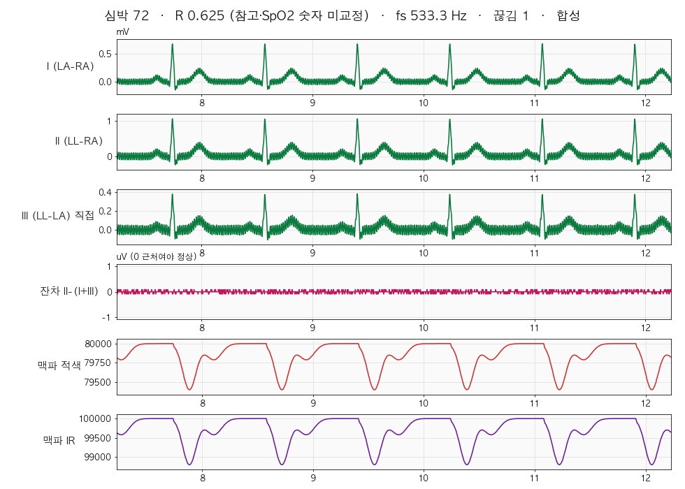
- Screen: white background, I · II · III · residual II−(I+III) · pulse wave red · pulse wave IR. Title shows heart rate (simple threshold method) · R ratio · fs · gaps · alarms
- Has a replay/inspection mode that re-decodes and checks saved files
Safety — before touching the human body
This test bench has no isolation. Module → ESP32 → USB → computer are electrically one piece.
- Laptop on battery only. Unplug the charger
- Do not plug any other cables into the laptop (HDMI monitor, Ethernet, external disk with power adapter, audio)
- Do not use an adapter-powered Raspberry Pi + display for body-electrode tests — only for the synthetic · short · simulator stages
- Do not plug directly into a grounded desktop and attach electrodes to the body
- While attached, do not touch metal desks · radiators · water pipes
- Do not attach over wet skin · wounds. Electrodes are disposable, single use
- Do not attach to people with pacemakers · implanted devices
- Do not judge health from this device's waveforms · numbers — it is a test bench
- Do not apply 5 V to the module (VDDIO max 3.6 V)
Test sequence
| Stage | What | Pass criterion |
|---|---|---|
| ① Synthetic | ESP32 only, over USB. Check the entire receiving path without the module (m s · n 50 · c 1) | Zero gaps · residual ≤ 2 LSB · heart rate 72 · 60 Hz amplitude equal in I · III and twice that in II |
| ② Shorted noise | Module connected, no electrodes. After confirming REVID=0x01, t 0 for 10 s · t + · t -, then tie the four electrodes to one point at the jack and t x | t 0 noise rms ≈ table value (2.07 µV rms in 533 mode) · t ± codes match expected values · no DRDYB warning · lead-off bits 0 |
| ③ Simulator | External battery simulator (1 V p-p → 1000:1 → 1 mV). Not yet built | 1 mV reads as 1 mV · residual at noise level (judges whether direct III measurement holds) · raw data saved before/after 60 Hz notch · lead-off response when removing electrodes one by one |
| ④ Human electrodes | After observing all the safety items above, 4 electrodes RA · LA · LL · RL | Lead-off 0 · RLD rail 0 · QRS visible · heart rate matches wrist pulse · residual 60 Hz amplitude recorded |
Always go through ② · ③ before ④. If a DRDYB warning appears in ② (suspected missing crystal), stop there.
14. Test-bench verification results (2026-10-11)
- Compilation passed for 2 variants, 0 warnings in test-bench sources (
--warnings all, arduino-cli 1.5.2-rc.1 · esp32 core 3.3.12)- Basic ESP32-S3 — flash 365,710 B (27 %) · RAM 24,336 B (7 %)
- Native USB CDC + OPI PSRAM + 16 MB — 366,348 B (27 %) · 25,016 B (7 %)
- No board upload was done (parts not yet arrived)
- Frame cross-verification: the same headers as the firmware (frames · synthetic signal) were compiled on a PC to generate a 20-second stream, which was decoded by the Python receiver
- Of 10,666 ECG frames, the one deliberately CRC-corrupted frame was correctly discarded (counted as 1 gap); 0 loss in 2,000 PPG frames
- Sync is not lost even when Korean text lines containing 0xA5 0xA5 bytes are mixed in
- Einthoven residual max 0.086 µV = 1 LSB, rms 0.042 µV → check passed
- CSV path (line parsing · seq gaps · flags) checked separately
Remaining unverified items (to check after parts arrive)
- ADS1293 module power configuration (VDD · VDDIO), presence of 4.096 MHz crystal, jack pin assignment, input protection · RLD component values
- Whether connecting one input pin simultaneously to CH1 + and CH3 − is allowed (judged by the residual)
- Whether the sensor module is a MAX30102, and whether red · IR are swapped
- Cross-check against the original MAX30102 datasheet
- RGB LED pin and USB port type of the ESP32-S3 board
- How many seconds the 8 nA lead-off takes to respond given cable capacitance
- Numeric limit for electrode DC current in medical standards